












NEWS
Blending Tank Acceptance Tests to Include in a Beverage Equipment RFQ
A blending tank RFQ should define acceptance by measurable process results: uniform composition within an agreed mixing time, cleanable product-contact surfaces, leak-free construction, and reliable temperature control where required. Rated capacity alone does not establish any of these. The test schedule should identify the test liquid, operating conditions, sampling locations, instruments, acceptance limits, and evidence required before shipment and after installation.
Separate factory acceptance testing (FAT) from site acceptance testing (SAT). Factory tests establish construction quality and performance under documented conditions. Site tests confirm that the installed tank works with the actual piping, utilities, controls, and beverage process. A factory water trial cannot establish blending performance for a viscous syrup or cleaning effectiveness against dried juice residue.
Define the test batch before comparing quotations
Acceptance limits become meaningful only when the operating envelope is fixed. State minimum and maximum working volumes separately from total vessel capacity. Include product viscosity at processing temperature, density differences between ingredients, solids content, addition sequence, and restrictions on foam or oxygen pickup. For carbonated beverages, specify the required pressure conditions and carbonation retention criteria.
Identify the mixing arrangement in the quotation: agitator, external recirculation loop, or a combination. For recirculation, include the pump, return-nozzle position, piping arrangement, and flow conditions in the test scope. Otherwise, a tank tested with a temporary factory pump could behave differently with the installed transfer circuit.
A substitute liquid needs a documented justification. Water with a soluble tracer is useful for evaluating liquid distribution, but it does not reproduce powder wetting, pulp suspension, or concentrated syrup dispersion. Where those duties determine suitability, include a representative process trial or reserve their acceptance for SAT.
Make blend uniformity a sampling test
Specify the measured property that represents successful blending. Soluble-solids concentration can suit syrup dilution; another formulation might require acidity, conductivity, or a specific ingredient assay. The measurement must distinguish the expected differences and remain reliable at the test temperature. Conductivity, for example, needs temperature compensation and a tracer concentration within the instrument’s useful range.
Collect samples from locations that expose poor circulation: upper, middle, and lower regions, plus the outlet where relevant. A single sample valve only demonstrates the composition at that point. Require an agreed sampling method that avoids stagnant sample lines and does not disturb the batch enough to conceal a dead zone.
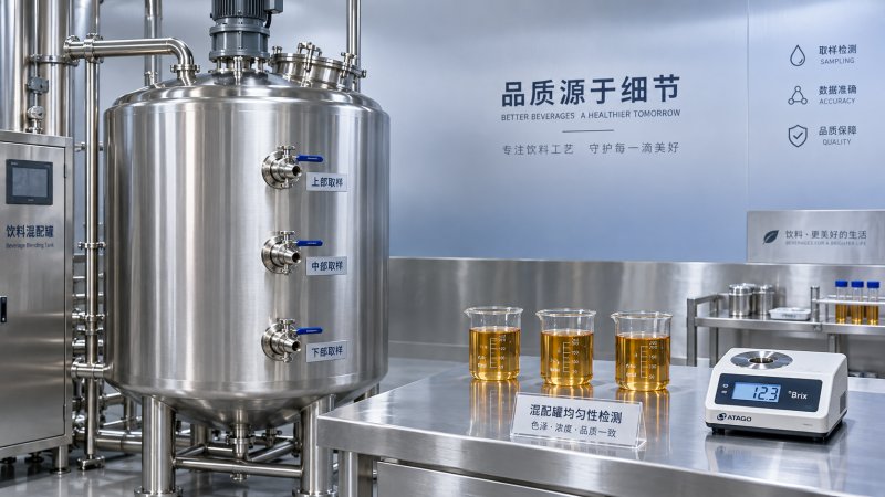
Define when the mixing clock starts, whether ingredient addition time is included, and whether mixing continues during sampling. Record agitator speed or recirculation flow, liquid temperature, fill level, and addition sequence. Test both ends of the required working-volume range: a full tank challenges circulation distance, while a low fill level can expose poor impeller immersion or excessive surface agitation.
The pass criterion should require every specified sample to meet the agreed composition tolerance within the maximum blending time. An acceptable average can conceal unacceptable local concentrations. State tolerances in units relevant to the recipe, and account for measurement uncertainty. Repeated readings after the first apparent pass help establish whether uniformity is stable.
If foam, oxygen pickup, or solids damage affects product quality, add a separate criterion and measurement method. Fast homogenization achieved through an unacceptable vortex is a failed result when oxygen control is part of the process requirement.
Verify materials and fabrication before closing access
Require material records traceable to the product-contact shell, bottom, nozzles, and other wetted components. Gaskets and valve seats also need identified materials and compatibility with the beverage and cleaning chemicals. Where positive material identification is specified, define its coverage and retain the results against component references.
Weld inspection should address internal finish, cracks, pits, incomplete fusion where detectable by the selected method, and crevices that retain product. Inspection photographs need location references. Specify which areas require visual examination and which require additional examination appropriate to the fabrication design; a generic statement that welds are “tested” leaves the scope unresolved.
Surface-finish acceptance needs a defined measurement method and locations, including representative weld areas. A polished shell does not establish the condition behind fittings or around a manway. Include records of the specified post-fabrication cleaning and surface treatment, together with inspection of inaccessible areas before assembly closes them.
For example, the listed 15000L stainless steel wine tanks include stainless steel 304 construction, a cooling jacket, a rotary spray ball, and a sloped bottom. Those features suggest material, jacket, spray-coverage, and drainage tests. The fermentation and storage description does not establish blending performance; any agitator or recirculation duty requires its own specification and trial.
Distinguish vessel, jacket, and valve leakage tests
The RFQ should require a written leak-test procedure identifying each test boundary, medium, pressure or liquid head, duration, instrument accuracy, and acceptance criterion. Vessel and jacket circuits have different design limits and must be tested accordingly. Test conditions must remain within the approved design and applicable test procedure; an atmospheric vessel must not be treated as pressure-rated equipment.
Record leakage observations at welds, fittings, manways, seals, and connections. Where valve isolation matters, include seat-leakage acceptance separately from external leakage. Inspect for permanent deformation after testing, and define any required examination of repaired areas.
A pressure/vacuum relief device requires verification against the approved vessel protection requirements. Its presence alone does not establish adequate protection during filling, draining, cooling, or cleaning. Installed vent paths and potential restrictions belong in SAT.
Prove cleaning coverage, then assess residue removal
A rotary spray ball demonstrates a cleaning provision, but its effectiveness depends on supply pressure, flow, position, and obstructions. Require a coverage test using an agreed visible or fluorescent tracer method. Include the manway underside, nozzle interiors, instrument fittings, and areas shadowed by internal components. Record cleaning-device inlet conditions during the test.
Coverage testing establishes that cleaning liquid reaches a surface. Residue-removal testing establishes whether the specified cleaning cycle removes the relevant soil. For juice, syrup, or other persistent deposits, define representative soil, exposure or drying conditions, cleaning chemistry, temperature, circulation time, and sampling locations.
Acceptance should use an agreed residue-detection method with a suitable detection limit. Final-rinse conductivity alone cannot establish that all beverage residue has been removed. Where microbiological validation is required, define it separately from physical cleanliness and spray coverage.
Include a drainage test with the tank in its intended installed orientation. Record retained liquid locations after the specified drain period, including valve cavities and connected piping. A sloped bottom loses its intended benefit if installation alignment or an elevated outlet creates pooling.
Match temperature and control tests to actual duties
For a jacketed blending tank, specify initial temperature, target temperature, batch volume, test-liquid properties, utility inlet temperature, and utility flow. Agree whether acceptance concerns cooling time, heating time, temperature uniformity, or all three. A temperature result without utility conditions cannot support a meaningful comparison.
Compare installed temperature readings with a calibrated reference and sample additional locations where stratification is plausible. Sensor accuracy and batch uniformity are separate results: a correctly calibrated probe can still sit in an unrepresentative region.
Functional testing should cover the installed control sequence, alarms, and relevant interlocks. Examples include preventing agitator operation below its permitted liquid level and verifying the defined response to sensor failure. Record actual equipment responses and restoration conditions.
Attach acceptance evidence and failure handling to the RFQ
Use an acceptance matrix to keep test obligations visible through quotation, fabrication, and commissioning.
State which failed tests block shipment or final acceptance, who supplies test materials, and who bears correction and retest costs. Require deviations to be recorded with their effect on the result. Final acceptance should follow closure of the agreed failures, with revised drawings and test records matching the equipment delivered.